Monday, December 28, 2009

CCIE Voice Lab 1.10 – Quality of Service

Quality of Service (QoS) will be the focus CCIE Voice Lab 1.10.

CCIE Voice Lab 1.10 Tasks

1. Ensure that Skinny traffic from New York to Los Angeles is set to DSCP CS3. Any and all markings should be done by the endpoint whenever possible.

2. Limit SCCP traffic in both New York and Los Angeles to 30k per endpoint, and exceed traffic should be remarked to AF11.

3. Configure the frame relay link between New York and Los Angeles as if it is a full T1 (1536kpbs) link. Ensure that MLP FLI is enabled on the link. Lastly, configure the QoS as follows:
a. Voice media traffic should have a 30% priority of link bandwidth;
b. Voice signaling traffic should be given 5% of the link bandwidth;
c. All other traffic should be treated with weighted fair queuing.

4. Configure the frame relay link between New York and Los Angeles as if it is a half- T1 (768 kbps) link, with the following QoS parameters:
a. Voice media traffic should have a 192K of link bandwidth prioritized;
b. Voice signaling traffic should be given 38K of the link bandwidth;
c. All other traffic should be treated with weighted fair queuing.

5. Ensure that the New York VGWY, Los Angeles VGWY, and London CUCME send signaling and media traffic at DSCP CS3 and EF respectively.

CCIE Voice Lab 1.10 Solutions

1. By default, SCCP DSCP values are set at CS3 in the CUCM Enterprise Parameters.


Next, identical QoS policies are configured on both the New York and London switches (3750 and NME-16ES-1G-P, respectively). First, enable QoS globally, then define the policed DSCP remarking:

mls qos
mls qos map policed-dscp 24 to 10


Then, create the appropriate access-list to identify the SCCP traffic, following by the class-map to match the traffic, and finally, the QoS policy.

!
access-list 101 permit tcp any any eq 2000
!
class-map match-all SCCP
match access-group 101
!
!
policy-map MARK-SCCP
class SCCP
set dscp cs3
police 30000 8000 exceed-action policed-dscp-transmit


The final step is to create an inbound service-policy for the switchports that have IP phones.

interface FastEthernet1/0/8
description newyork phones
switchport access vlan 11
switchport voice vlan 12
spanning-tree portfast
service-policy input MARK-SCCP


2. The QoS and Traffic Shaping described in task 3 requires the creation Modular QoS CLI, a Virtual Template, and Frame Relay traffic shaping on both the New York and Los Angeles routers. Note, the configurations are identical on both routers, with the exception of the IP Addressing on both sides of the link. The first step it to create the QoS policy.

class-map match-all SIGNAL
match ip dscp cs3
class-map match-all RTP
match ip dscp ef
!
!
policy-map NY-LA-QOS
class RTP
priority percent 30
class SIGNAL
bandwidth percent 5
class class-default
fair-queue

Next, create the Virtual Templates for both New York and Los Angeles. Below is the New York side of the link.

!
interface Virtual-Template102
bandwidth 1536
ip address 172.16.1.1 255.255.255.252
ip ospf network point-to-point
ppp multilink
ppp multilink interleave
ppp multilink fragment delay 10
service-policy output NY-LA-QOS
!

Then, create the frame relay traffic shaping policy, and associate the Virtual Template with the Frame Relay sub-interface, and associate the frame relay traffic shaping policy.

!
map-class frame-relay FRTS-NY-LA
frame-relay cir 1536000
frame-relay bc 15360
frame-relay be 0
frame-relay mincir 1536000
!
interface Serial0/2/0
no ip address
encapsulation frame-relay
frame-relay traffic-shaping
frame-relay lmi-type cisco
!
interface Serial0/2/0.102 point-to-point
description frame relay link to Los Angeles
ip ospf network point-to-point
frame-relay interface-dlci 102 ppp Virtual-Template102
class FRTS-NY-LA
!


3. The QoS configuration between New York and London is slightly different, since the tasks do not instruct us to configure MLP LFI. For this link, the QoS policy-map is defined, reusing the previously configured class-maps. Then, a frame-relay traffic shaping policy is defined, with the QoS service-policy tied to it. Lastly, the FRTS policy is associated with the frame-relay sub-interfaces between New York and London.

!
policy-map NY-LNDN-QOS
class RTP
priority 192
class SIGNAL
bandwidth 38
class class-default
fair-queue
!
!
map-class frame-relay FRTS-NY-LNDN
frame-relay cir 768000
frame-relay bc 7680
frame-relay be 0
frame-relay mincir 768000
service-policy output NY-LNDN-QOS
!
!
interface Serial0/2/0.103 point-to-point
description frame relay link to London
ip address 172.16.1.5 255.255.255.252
ip ospf network point-to-point
frame-relay interface-dlci 103
class FRTS-NY-LNDN
!

4. By default, the MGCP and H323 gateways send media (RTP) marked as ef and signaling marked as af31.

To verify New York, first issue:

newyork#sh dial-peer voice 100 include DSCP
ip media DSCP = ef, ip media rsvp-pass DSCP = ef
ip media rsvp-fail DSCP = ef, ip signaling DSCP = cs3,
ip video rsvp-none DSCP = af41,ip video rsvp-pass DSCP = af41
ip video rsvp-fail DSCP = af41,

Then, modify the markings for each VOIPdDial-peer. Dial-peer 100 is shown below.

newyork(config)#dial-peer voice 100
newyork(config-dial-peer)#ip qos dscp cs3 signaling

In Los Angeles, verify by issuing a “show mgcp” to view the defaults.

losangeles#sh mgcp
!
MGCP media (RTP) dscp: ef, MGCP signaling dscp: af31


To modify, issue

losangeles(config)#mgcp ip qos dscp ef media
losangeles(config)#mgcp ip qos dscp cs3 signaling


then verify

losangeles#sh mgcp
!
MGCP media (RTP) dscp: ef, MGCP signaling dscp: cs3

CUCME marks voice media traffic at DSCP value EF by default and voice signaling DSCP value CS3 by default. These parameters may be changed under the telephony-service CLI parameters. A “show telephony-service” in London verifies the values.

london#sh telephony-service
CONFIG (Version=7.1)
=====================
Version 7.1
Cisco Unified Communications Manager Express
For on-line documentation please see:
http://www.cisco.com/en/US/products/sw/voicesw/ps4625/tsd_products_support_series_home.html

ip source-address 10.1.32.1 port 2000
ip qos dscp:
ef (the MS 6 bits, 46, in ToS, 0xB8) for media
cs3 (the MS 6 bits, 24, in ToS, 0x60) for signal
af41 (the MS 6 bits, 34, in ToS, 0x88) for video
default (the MS 6 bits, 0, in ToS, 0x0) for serviceservice directed-

Wednesday, December 16, 2009

CCIE Voice Lab 1.9 – Conferencing, Transcoding, and MTP Resources

CCIE Voice Lab 1.9 requires the set up and configuration of Conferencing, Transcoding, and MTP Resources for Ballplayers, LLC.


CCIE Voice Lab 1.9 Tasks

1. For New York users, configure conferencing resources on the New York VGWY first, followed by the PUB, then SUB.

2. For LA users, configure conferencing resources on the LA VGWY first, followed by the PUB, then SUB.

3. Allow a maximum of 8 users in a conference bridge session. Ensure that when the Conference Controller leaves an AdHoc Conference, the call is dropped.

4. For each location, configure a MeetMe conference bridge using an x100 DN, where x= the appropriate dial plan for each location.

5. For both NY and LA, configure local transcoding resources.

6. Configure the London CUCME router to provide local transcoding and both MeetMe and AdHoc conferencing resources for users. Users should have a distinct join and leave tone.

7. Enable MOH for all three locations. Ensure that MOH files are available in G.711ulaw, G.729, and Wideband. Ensure the MOH loops.


CCIE Voice Lab 1.9 Solutions

The tasks in lab 1.9 require configuration in both the CUCM and VGWYs. The IOS commands will be covered first, followed by the CUCM, and lastly the London CUCME configuration.

1. The first step is to configure the DSP services on the New York and Los Angeles. The configurations on both VGWYs are nearly identical, with one exception pertaining to MOH in Los Angeles. That exception will be discussed separately later.

Essentially, you enable dspfarm services, followed by creating dspfarm profiles, and then associating those profiles with SCCP. The NY VGWY configuration is as follows:

newyork#sh run
!
voice-card 0
dspfarm
dsp services dspfarm
!
!
sccp local Loopback0
sccp ccm 10.1.10.21 identifier 2 version 7.0
sccp ccm 10.1.10.20 identifier 1 version 7.0
sccp
!
sccp ccm group 1
associate ccm 1 priority 1
associate ccm 2 priority 2
associate profile 2 register NY-VGWY-TRANS
associate profile 1 register NY-VGWY-CONF
!
dspfarm profile 2 transcode
codec g711ulaw
codec g711alaw
codec g729ar8
codec g729abr8
codec g722-64
codec g729br8
codec g729r8
maximum sessions 2
associate application SCCP
!
dspfarm profile 1 conference
codec g711ulaw
codec g711alaw
codec g729ar8
codec g729abr8
codec g729r8
codec g729br8
codec g722-64
maximum sessions 2
associate application SCCP
!

newyork# sh sccp
SCCP Admin State: UP
Gateway Local Interface: Loopback0
IPv4 Address: 1.1.1.1
Port Number: 2000
IP Precedence: 5
User Masked Codec list: None
Call Manager: 10.1.10.21, Port Number: 2000
Priority: N/A, Version: 7.0, Identifier: 2
Trustpoint: N/A
Call Manager: 10.1.10.20, Port Number: 2000
Priority: N/A, Version: 7.0, Identifier: 1
Trustpoint: N/A

Transcoding Oper State: ACTIVE - Cause Code: NONE
Active Call Manager: 10.1.10.20, Port Number: 2000
TCP Link Status: CONNECTED, Profile Identifier: 2
Reported Max Streams: 4, Reported Max OOS Streams: 0
Supported Codec: g711ulaw, Maximum Packetization Period: 30
Supported Codec: g711alaw, Maximum Packetization Period: 30
Supported Codec: g729ar8, Maximum Packetization Period: 60
Supported Codec: g729abr8, Maximum Packetization Period: 60
Supported Codec: g722r64, Maximum Packetization Period: 30
Supported Codec: g729br8, Maximum Packetization Period: 60
Supported Codec: g729r8, Maximum Packetization Period: 60
Supported Codec: rfc2833 dtmf, Maximum Packetization Period: 30
Supported Codec: rfc2833 pass-thru, Maximum Packetization Period: 30
Supported Codec: inband-dtmf to rfc2833 conversion, Maximum Packetization Period: 30

Conferencing Oper State: ACTIVE - Cause Code: NONE
Active Call Manager: 10.1.10.20, Port Number: 2000
TCP Link Status: CONNECTED, Profile Identifier: 1
Reported Max Streams: 16, Reported Max OOS Streams: 0
Supported Codec: g711ulaw, Maximum Packetization Period: 30
Supported Codec: g711alaw, Maximum Packetization Period: 30
Supported Codec: g729ar8, Maximum Packetization Period: 60
Supported Codec: g729abr8, Maximum Packetization Period: 60
Supported Codec: g729r8, Maximum Packetization Period: 60
Supported Codec: g729br8, Maximum Packetization Period: 60
Supported Codec: g722r64, Maximum Packetization Period: 30
Supported Codec: rfc2833 dtmf, Maximum Packetization Period: 30
Supported Codec: rfc2833 pass-thru, Maximum Packetization Period: 30
Supported Codec: inband-dtmf to rfc2833 conversion, Maximum Packetization Period: 30


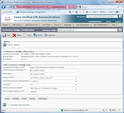
2. Borrowing from the concepts of Gateways > Route Groups > Route Lists, first define the conference bridges and trancoding resources.


Next, define Media Resource Groups (MRG) and assign the conference bridges and trancoding resources accordingly. I’ve created a MRG for each location; New York and Los Angeles.


The MRGs are then added to a Media Resource Groups List (MRGL); one for each location. Watch the ordering, so that HW resources are used prior to SW resources.


Finally, assign the appropriate MRGL to the appropriate Device Pool for each location.


3. Configuring conferencing and transcoding resources for the London CUCME router is nearly identical to as configuring the resources on the NY and LA VGWYs. However, SSCP is associated with CUCME under telephony-service, rather than the UCMs. Rather than revisit the configuration, refer to CUCME-CUE Lab 7 – CUCME Conferencing & Transcoding. I assigned dn 3100 for the MeetMe bridge and 3101 for the AdHoc bridge.

4. There are few tricks for the MOH, specifically for the LA SIP-based location. First, make sure that the “Cisco IP Voice Media Streaming App” is activated under Cisco Unified Serviceability.

Next, make sure that G.711ulaw, G.729, and Wideband are selected under the Service Parameters > Cisco IP Voice Media Streaming App.


The MOH servers are then assigned to the MRGs; see the NY MRG screenshot above. To quickly assign the same MOH file to all phones, go to Device > Device Settings > Common Device Configuration, and create a custom configuration. I’ve chosen “1952 Vincent Black Lightning” from Alt-County band “Reckless Kelly”.


This newly created “MOH Common Device Configuration” can now be assigned to each phone.


When testing MOH up to this point, I noticed the phones based in Los Angeles were not receiving MOH. After some research, I discovered the MOH for SIP phones needs to terminate on an MTP resource on the LA VGWY. Therefore, one additional dspfarm profile is required for the LA VGWY, along with its companion configuration in UCM. This MTP is then assigned to the LA MRG.

losangeles#sh run
!
sccp ccm group 1
associate ccm 1 priority 1
associate ccm 2 priority 2
associate profile 3 register LA-VGWY-MTP
associate profile 1 register LA-VGWY-CONF
associate profile 2 register LA-VGWY-TRANS
!
!
dspfarm profile 3 mtp
codec g711ulaw
maximum sessions software 2
associate application SCCP
!


Wednesday, November 25, 2009

CCIE Voice Lab 1.8 – SRST and AAR

This lab will challenge the candidate to configure Survivable Remote Site Telephony (SRST) and Automated Alternate Routing (AAR).

CCIE Voice Lab 1.8 Tasks

1. Configure the Los Angeles router for SIP SRST. Phone should display a “SRST Fallback Active” message.

2. While in SRTS mode, calls to 911 or 9-911 should be route immediately. You may only use on outgoing dial-peer to accomplish this task.

3. Preserve the dial-9 for PSTN access during an SRST scenario.

4. While in SRST node, users should be able to dial 4-digit to NY and 7+3… to London. Calls should be routed over the PSTN without the need for users to add prefixes to these locations. You may not use a Prefix in the dial-peer, and this task must be accomplished using a minimal amount of commands.

5. Ensure that users at New York and Los Angeles are able to call each other when bandwidth limits are met.


CCIE Voice Lab 1.8 Solutions

1. Tasks 1 – 4 involved setting up SRST for SIP phones. A very good reference document is the Cisco Unified SIP SRST System Administrator Guide . First, start by configuring the basis SRST commands on the Los Angeles VGWY.

losangeles#
!
voice register global
system message SRST Fallback Active
max-dn 10
max-pool 10
dialplan-pattern 1 2135432... extension-length 4
!
voice register pool 1
translation-profile incoming emergency
id mac 0021.D8B9.BC72
number 1 2001
codec g722-64
!
voice register pool 2
translation-profile incoming emergency
id mac 0021.D8BA.2373
number 1 2002
codec g722-64
!
!
application
global
service alternate default
!
!
ccm-manager fallback-mgcp
!
!
call-manager-fallback
max-conferences 4 gain -6
transfer-system full-consult
!


2. To configure 911 and 9-911 routing, configure 9-911 translation rule and translation profile. Then, apply the translation profile to the voice register pool configurations. Lastly, create a 911 pots dial-peer.

!
voice translation-rule 1
rule 1 /9911/ /911/
!
!
voice translation-profile emergency
translate called 1
!
!
voice register pool 1
translation-profile incoming emergency
!
voice register pool 2
translation-profile incoming emergency
!
!
dial-peer voice 911 pots
description SRST 911
destination-pattern 911
port 0/1/0:23
forward-digits all
!

3. Task 3 and 4 involve the creation of additional pots dial-peers. However, you need to create some additional translation rules and a translation profile to accommodate the 4-digit and 7+4-digit dialing requirements.

!
voice translation-rule 2
rule 1 /\(1...\)/ /212432\1/
rule 2 /^7\(3...\)/ /207654\1/
!
!
voice translation-profile SRST
translate called 2
!
!
dial-peer voice 2 pots
description SRST Long Distance
destination-pattern 91[2-9]..[2-9]......
incoming called-number .
direct-inward-dial
port 0/1/0:23
!
dial-peer voice 3 pots
description SRST Local 10-Digit
destination-pattern 9[2-9]..[2-9]......
port 0/1/0:23
!
dial-peer voice 4 pots
description SRST London
destination-pattern 901144T
port 0/1/0:23
!
dial-peer voice 5 pots
description SRST 4-digit to NY
translation-profile outgoing SRST
destination-pattern 1...
port 0/1/0:23
!
dial-peer voice 6 pots
description SRST 7+4-digit to London
translation-profile outgoing SRST
destination-pattern 73...
port 0/1/0:23
!


4. Test the SIP SRST fallback by shutting down the WAN link from Los Angeles to New York. First, the phones should failover to SRST and display the “SRST Fallback Active” message. The “show voice register all” will provide the SRST configuration. Lastly, place some test calls, using 4-digit, 7+4-digit, and PSTN dial patterns.

losangeles# sh voice register all
VOICE REGISTER GLOBAL
=====================
CONFIG [Version=7.1]
========================
Version 7.1
Mode is srst
Max-pool is 10
Max-dn is 10
Outbound-proxy is enabled and will use global configured value
System message is SRST Fallback Active
timeout interdigit 10
network-locale[0] US (This is the default network locale for this box)
network-locale[1] US
network-locale[2] US
network-locale[3] US
network-locale[4] US
user-locale[0] US (This is the default user locale for this box)
user-locale[1] US
user-locale[2] US
user-locale[3] US
user-locale[4] US

VOICE REGISTER DN
=================

VOICE REGISTER POOL
===================
Pool Tag 1
Config:
Mac address is 0021.D8B9.BC72
Number list 1 : Pattern is 2001
Proxy Ip address is 0.0.0.0
DTMF Relay is disabled
kpml signal is enabled
Translation-profile incoming emergency

Dialpeers created:

dial-peer voice 40003 voip
destination-pattern 2001
redirect ip2ip
session target ipv4:10.1.22.16:5060
session protocol sipv2
digit collect kpml
codec g722-64 bytes 160
after-hours-exempt FALSE

dial-peer voice 40004 voip
destination-pattern 2135432001
redirect ip2ip
session target ipv4:10.1.22.16:5060
session protocol sipv2
digit collect kpml
codec g722-64 bytes 160
after-hours-exempt FALSE

Statistics:
Active registrations : 1

Total SIP phones registered: 1
Total Registration Statistics
Registration requests : 1
Registration success : 1
Registration failed : 0
unRegister requests : 0
unRegister success : 0
unRegister failed : 0


Pool Tag 2
Config:
Mac address is 0021.D8BA.2373
Number list 1 : Pattern is 2002
Proxy Ip address is 0.0.0.0
DTMF Relay is disabled
kpml signal is enabled
Translation-profile incoming emergency

Dialpeers created:

dial-peer voice 40001 voip
destination-pattern 2002
redirect ip2ip
session target ipv4:10.1.22.17:5060
session protocol sipv2
digit collect kpml
codec g722-64 bytes 160
after-hours-exempt FALSE

dial-peer voice 40002 voip
destination-pattern 2135432002
redirect ip2ip
session target ipv4:10.1.22.17:5060
session protocol sipv2
digit collect kpml
codec g722-64 bytes 160
after-hours-exempt FALSE

Statistics:
Active registrations : 1

Total SIP phones registered: 1
Total Registration Statistics
Registration requests : 1
Registration success : 1
Registration failed : 0
unRegister requests : 0
unRegister success : 0
unRegister failed : 0


5. The final tasks require the configuration of setup and configuration of Automated Alternate Routing (AAR). AAR is disabled by default on CUCM, so the first step is to configure the AAR Service Parameters in CUCM by choosing System > Service Parameters > Cisco Call Manager.

Next, configure an AAR group. Since my Adtran PSTN simulator does not accept the “1” for long distance calls, I simply prefix a “9”. In the CCIE Voice Lab, and possibly your home lab, you may need to prefix “91”.


AAR Partitions and Calling Search Spaced are then created for AAR. Below is the NY AAR CSS, which included the NY AAR LD Partition.


Two new Route Lists are created, one for each location. These new route lists used for the AAR only point to the local PSTN gateways. Below is the NY AAR RL.


Create two new route patterns for ten-digit NY to LA and LA to NY calling (remember, my Adtran PSTN simulator does not accept “1+10-digit” dialing). Link these new route patterns to the appropriate AAR Route lists.


Finally, add the appropriate AAR Calling Search Space and AAR Group to each phone and AAR settings for line.


For testing, I temporary modify the bandwidth between locations to 24kbps (one call). Nail up two calls between each location. With the second call, the phone should display “Network Congestion, Rerouting” and the call should be placed via the PSTN.

Thursday, November 19, 2009

CCIE Voice Lab 1.7 – Voice CODECs and CAC

Now that the dial plan has been properly configured between New York, Los Angeles, and London, this lab will focus on configuring the proper CODECs between locations as well as Call Admission Control.

CCIE Voice Lab 1.7 Tasks
1. Calls within a location should use G.722 wideband.

2. Calls between locations should use G.729.

3. Allow five concurrent calls between New York and Los Angeles.

4. When calls from London to either New York or LA use the IP WAN, they should negotiate G.729. However, in the event that there are any transcoding issues, only one G.722 call should be allowed across the WAN.


CCIE Voice Lab 1.7 Solutions
The tasks in this lab are relatively simple. A good discussion on locations, regions, and CAC are covered Call Admission Control chapter of Cisco Unified Communications SRND Based on Cisco Unified Communications Manager 7.x. You can also click here and here for some old, but decent Gatekeeper configuration examples.

1. The first step is to create regions for New York, Los Angeles, and London and assign the codecs to be used between each location. You may have done some of these task earlier when configure phones.

2. Next, create Device Pools and assign the Regions accordingly.

3. Next, assign your newly create device pools to devices.

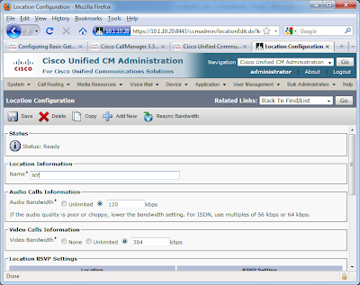
4. Create your locations and assign the appropriate bandwidth. Make sure you understand how CUCM allocates bandwidth for a particular codec. Then, assign these locations to the Phones.


5. On the gatekeeper, configure the proper bandwidth settings.

newyork#
!
gatekeeper
zone local newyork ballplayersllc.com 1.1.1.1
alias static 10.1.10.21 1720 gkid newyork gateway voip ras 10.1.10.21 33072 e164 2002 e164 2001 e164 1003 e164 1002 e164 1001
bandwidth total zone newyork 128
no shutdown


6. Finally, nail up some calls between locations to exceed the bandwidth limits. On CUCM phones, once bandwidth limits are hit, the phones should display “Not Enough Bandwidth”. On the gatekeeper, “debug ras” and “show gatekeeper zone status” are useful commands.

Tuesday, November 10, 2009

CCIE Voice Lab 1.6 – Call Routing

This lab focuses on developing the Call Routing and dial plan for Ballplayers, LLC. Please note, depending on your PSTN simulation, some task may require digit manipulation not explicitly defined in the tasks. For example, my Adtran does not accept the London international dial plan. Therefore, I will need to strip the 011+44 from the international dialing from New York and Los Angeles. Your solution may vary, depending on what you are using to simulate the PSTN, and what digits that device will accept.

CCIE Voice Lab 1.6 Tasks

1. Ari Gold (1001) and Arliss Michaels (2001) are allowed full dialing privileges, including international. David Wright (1002) and Kobe Bryant (2002) are not allowed international dialing. Finally, Eli Manning can only call on-net calls.

2. New York should be configured with the following call routing options and parameters:

Calls to London: 7+4 digits
Emergency: 911 and 9911
Local: 9+10 digits
Long Distance: 9+1+10 digits
International: 9+011+any number of digits

In addition:

2a. Local calls from New York should user the local VGWY, followed by the Los Angeles VGWY.

2b. Long Distance calls from New York should user the local VGWY, followed by the LA VGWY.

2c. Calls from NY to the LA area code (213) should route via the LA VGWY, followed by the NY VGWY.

2d. International calls to London from NY should use the 7+4 digit pattern via the gatekeeper, followed by the local NY VGWY. Users should not receive secondary dial-tone when calling London extensions.

2e. All other International calls should route via the NY VGWY, followed by the LA VGWY. Eli should be able to call London an on-net call.

3. Los Angeles should be configured with the following call routing options and parameters:

Calls to London: 7+4 digits
Emergency: 911 and 9911
Local: 9+10 digits
Long Distance: 9+1+10 digits
International: 9+011+any number of digits

In addition:

3a. Local calls from LA should user the local VGWY, followed by the NY VGWY.

3b. Long Distance calls from LA should user the local VGWY, followed by the NY VGWY.

3c. Calls from LA to the NY area code (212) should route via the NY VGWY, followed by the LA VGWY.

3d. International calls to London from LA should use the 7+4 digit pattern via the gatekeeper, followed by the local LA VGWY. Users should not receive secondary dial-tone when calling London extensions.

3e. All other International calls should route via the LA VGWY, followed by the NY VGWY. Eli should be able to call London an on-net call.

4. The London dial plan should be configured as follows:

Calls to New York and Los Angeles: 7+4 digits
Emergency: 999 and 9999
Local London: 9+8 digits
Long Distance UK: 9+0+8 digits
International to US: 9+001+any number of digits


5. You may not use any call blocking mechanisms or local routing to accomplish the task in this lab.

6. You may not use the 9.@ NANP wildcard.

7. All external callers should receive the proper E.164 Call ID from the Calling Party.


CCIE Voice Lab 1.6 Solutions
There are three ways to design a dial plan:

• The Traditional Partition/Calling Search Space approach
• The Line/Device CSS approach
• The New Local Route Groups approach

The wording of this lab, in particular task 5 disallowing the use of blocking mechanism and local routing is an attempt to force the user to configure the dial plan using the Traditional Partition/Calling Search Space approach. The dial plan configuration for both New York and Los Angeles is very similar, so the steps below apply to both.

1. First, begin by creating the appropriate partitions for each location.


2. Next, create the Calling Search Spaces (CSS) and assign the Partitions accordingly


3. Route groups are configured next. For each respective route group, only assign the local gateway. For example, for “RG_LA_MGCP_VGWY” only assign the LA VGWY; for RG_NY_H323_VGWY only assign the NY VGWY; and for RG_GKPR only assign gatekeeper trunk configured in the previous lab.

One note about this lab…. During my testing and staging, I ended up removing the Technology Prefix that was required in Lab 1.5. Therefore, you will need to remove this configuration from the trunk as well as the Gatekeeper.


4. The Route Groups are then added to Route Lists. Pay attention to the ordering of the Route Lists in the Route Groups, so that the task requirements are met. For example, below is the ordering for the LA to NY Tail End Hop Off (TEHO) described in the tasks.


5. The Route Patterns are created next, and assigned to the appropriate Route Lists. Here, your configuration may vary slightly from mine, based on your particular PSTN simulator.


For example, in my Adtran only accepts 10-digit dialing (or, at least that is all I could figure it out to accept). Therefore, I apply a “XXXXXXXXXX” mask so that only the trailing ten digits of a call to London is sent. In this example, if a user in NY dials 9-011-44-20-7654-3001, only “20-7654-3001”, which my Adtran then routes to the London PRI. Don’t forget thing such as “Urgent Priority” for 911 and selecting Discard Digits options where appropriate.


6. Lastly, assign the phones and lines to their appropriate partitions in order to honor the Class of Service described in the task.

7. Networking between CUCM and CUCME can be tricky, especially given the tasks as described. For the 7+4-digit dialing, you need to create a translation rule. A rule is also required to add the appropriate prefix to route calls out the PSTN. Finally, for my testing purpose, I create a rule to translate “999” to “911” so that I could test 911 emergency call to my Adtran.

Another helpful hint during testing is to change the preferences of the dial-peer and observe the behavior of the phone class using the “sh voice call summary” command.

!
voice service voip
allow-connections h323 to h323
allow-connections h323 to sip
allow-connections sip to h323
allow-connections sip to sip
supplementary-service h450.12
h323
!
!
!
voice class codec 1
codec preference 1 g729r8
codec preference 2 g722-64
codec preference 3 g711ulaw
codec preference 4 g711alaw
!
!
translation-rule 1
Rule 1 71 1
Rule 2 72 2
!
!
translation-rule 2
Rule 0 ^999 911
!
!
translation-rule 3
Rule 1 71 2124321
Rule 2 72 2135432
!
!
dial-peer voice 1 pots
description inbound PRI dial-peer
incoming called-number .
direct-inward-dial
port 0/0/0:23
!
dial-peer voice 999 pots
destination-pattern 999
translate-outgoing called 2
port 0/0/0:23
forward-digits 3
!
dial-peer voice 2 pots
description International
destination-pattern 9001T
port 0/0/0:23
!
dial-peer voice 3 pots
description London Local
destination-pattern 9[2-9].......
port 0/0/0:23
!
dial-peer voice 4 pots
description UK Long Distance
destination-pattern 90[2-9].......
port 0/0/0:23
!
dial-peer voice 1000 voip
preference 2
destination-pattern 71...
translate-outgoing called 1
voice-class codec 1
session target ras
dtmf-relay h245-alphanumeric
!
dial-peer voice 2000 voip
preference 2
destination-pattern 72...
translate-outgoing called 1
voice-class codec 1
session target ras
dtmf-relay h245-alphanumeric
!
dial-peer voice 1001 pots
preference 1
destination-pattern 71...
translate-outgoing called 3
port 0/0/0:23
!
dial-peer voice 2001 pots
preference 1
destination-pattern 72...
translate-outgoing called 3
port 0/0/0:23
!

Friday, October 16, 2009

CCIE Voice Lab 1.5 – Voice Gateways

In CCIE Voice Lab 1.5, tasks will involved configuring the voice gateways in New York, Los Angeles, and London. To conserve DSP resources in my lab, I am only configuring 3 channels per voice gateway.

CCIE Voice Lab 1.5 Tasks

1. Configure the New York voice gateway as an H.323 gateway, and register with CUCM.

2. Configure Los Angeles as an MGCP gateway. However, you cannot use the “ccm-manager config server” command. If the primary CUCM goes down, make sure all endpoints on the MGCP gateway re-register to the backup CUCM.

3. Configure PSTN connectivity for London.

4. Configure the New York voice gateway as a gatekeeper. Register the CUCM servers and London CUCME router to the gatekeeper. The CUCM servers should register with the technology prefix of “1” and the London CUCME router should register with technology prefix “2”.

5. Verify inbound calling from the PSTN.


CCIE Voice Lab 1.5 Solutions

1. First step in adding the New York VGWY to CUCM is to configure the appropriate parameters in the router, including the VWIC module and dial-plan configurations.

newyork#
!
card type t1 0 0
!
network-clock-participate wic 0
!
isdn switch-type primary-ni
!
!
voice class codec 1
codec preference 1 g722-64
codec preference 2 g711ulaw
codec preference 3 g711alaw
codec preference 4 g729r8
!
!
voice class h323 1
h225 timeout tcp establish 3
!
!
controller T1 0/0/0
cablelength long 0db
pri-group timeslots 1-3,24
!
!
!
interface FastEthernet0/0.12
description New York Voice VLAN
encapsulation dot1Q 12
ip address 10.1.12.1 255.255.255.0
h323-gateway voip interface
h323-gateway voip bind srcaddr 10.1.12.1
!
!
dial-peer voice 1 pots
description inbound PRI dial-peer
incoming called-number .
direct-inward-dial
port 0/0/0:23
!
dial-peer voice 100 voip
description Voip DialPeer to UCMSUB01
preference 1
destination-pattern 2124321...
voice-class codec 1
voice-class h323 1
session target ipv4:10.1.10.21
incoming called-number .
dtmf-relay h245-alphanumeric
!
dial-peer voice 101 voip
description Voip DialPeer to UCMPUB01
preference 2
destination-pattern 2124321...
voice-class codec 1
voice-class h323 1
session target ipv4:10.1.10.20
incoming called-number .
dtmf-relay h245-alphanumeric
!
dial-peer voice 2 pots
destination-pattern 9T
port 0/0/0:23
!


Next, add the voice gateway to CUCM. Do not forget to modify the significant digits that CUCM receives for inbound calls.


2. The instructions for adding Los Angeles as an MGCP voice gateway explicitly tell us NOT to use the the “ccm-manager config server” command. Therefore, we need to manually configure the MGCP information on the router.

losangeles#
!
card type t1 0 1
!
network-clock-participate wic 1
!
isdn switch-type primary-ni
!
!
controller T1 0/1/0
cablelength long 0db
pri-group timeslots 1-3,24 service mgcp
!
!
interface Serial0/1/0:23
no ip address
encapsulation hdlc
isdn switch-type primary-ni
isdn incoming-voice voice
isdn bind-l3 ccm-manager
no cdp enable
!
!
ccm-manager switchback immediate
ccm-manager redundant-host 10.1.10.20
ccm-manager mgcp
ccm-manager fax protocol cisco
!
mgcp
mgcp call-agent 10.1.10.21 service-type mgcp version 0.1
mgcp fax t38 ecm
mgcp bind control source-interface Vlan22
mgcp bind media source-interface Vlan22
!
mgcp profile default
!
!
!
dial-peer voice 1 pots
service mgcp
incoming called-number .
direct-inward-dial
port 0/1/0:23
!
dial-peer voice 2 pots
service mgcp
destination-pattern 9T
port 0/1/0:23
!


Next, add the router as an MGCP gateway. Again, make sure to modify the significant digits that CUCM receives for inbound calls.


3. Configuring the PSTN and Dial Peers in London is fairly straight forward. Please note, I could not configure my Adtran Atlass 550 to accept the international dial-plan (44-20-7654-3XXX). As a result, I’ve modified the Adtran to accept 20-7654-3XXX. As for the 44 international code for London, I will work around this issue later (TBD).

london#
!
card type t1 0 0
!
network-clock-participate wic 0
!
isdn switch-type primary-ni
!
!
!
controller T1 0/0/0
cablelength short 110
pri-group timeslots 1-3,24
!
!
dial-peer voice 1 pots
description inbound PRI dial-peer
incoming called-number .
direct-inward-dial
port 0/0/0:23
!
dial-peer voice 2 pots
destination-pattern 9T
port 0/0/0:23
!


4. The final gatekeeper configuration requires a little care. First, pay attention to the wording regarding the technology prefix task. Habit may be to add the “#” sign; however the task instructions state only to add a “1” or “2”. Adding the “#” would result in points lost. Also, because the New York VGWY has been added to CUCM with the 10.1.12.1 IP address, you need to use a different IP for gatekeeper.

newyork#
!
gatekeeper
zone local newyork ballplayersllc.com 1.1.1.1
zone local london ballplayersll.com
gw-type-prefix 1* gw ipaddr 10.1.10.21 1720 gw ipaddr 10.1.10.20 1720
gw-type-prefix 2* gw ipaddr 3.3.3.3 1720
no shutdown
!

london#
!
interface Loopback0
ip address 3.3.3.3 255.255.255.0
ip ospf network point-to-point
h323-gateway voip interface
h323-gateway voip id newyork ipaddr 1.1.1.1 1719
h323-gateway voip h323-id london
h323-gateway voip tech-prefix 2
!
gateway
timer receive-rtp 1200
!
Next, add the Gatekeeper and Gatekeeper Controller Trunk to CUCM.


newyork#sh gatekeeper endpoints
GATEKEEPER ENDPOINT REGISTRATION
================================
CallSignalAddr Port RASSignalAddr Port Zone Name Type Flags
--------------- ----- --------------- ----- --------- ---- -----
3.3.3.3 1720 3.3.3.3 63826 newyork VOIP-GW
H323-ID: london
E164-ID: 3001
E164-ID: 3002
E164-ID: 3003
E164-ID: 3004
E164-ID: 3005
E164-ID: 3333
E164-ID: 2076543001
E164-ID: 2076543002
E164-ID: 2076543003
E164-ID: 2076543004
E164-ID: 2076543005
E164-ID: 2076543333
Voice Capacity Max.= Avail.= Current.= 0
10.1.10.20 41390 10.1.10.20 32833 newyork VOIP-GW
H323-ID: trunk_to_newyork_gkpr_1
Voice Capacity Max.= Avail.= Current.= 0
10.1.10.21 36152 10.1.10.21 32821 newyork VOIP-GW
H323-ID: trunk_to_newyork_gkpr_2
Voice Capacity Max.= Avail.= Current.= 0
Total number of active registrations = 3

newyork#sh gatekeeper gw-type-prefix
GATEWAY TYPE PREFIX TABLE
=========================
Prefix: 1*
Statically-configured gateways (not necessarily currently registered):
10.1.10.21:1720
10.1.10.20:1720
Zone newyork master gateway list:
10.1.10.20:41390 trunk_to_newyork_gkpr_1
10.1.10.21:36152 trunk_to_newyork_gkpr_2

Prefix: 2*
Statically-configured gateways (not necessarily currently registered):
3.3.3.3:1720
Zone newyork master gateway list:
3.3.3.3:1720 london

5. Each location should now be able to receive inbound calls from the PSTN. However, since a dial plan has yet to be configured on CUCM, only London can dial out.

Wednesday, October 7, 2009

CCIE Voice Lab 1.4 – CUCME London

Lab 1.4 focuses on setting up Cisco Unified Communications Manager Express for Ballplayers LLC’s London, UK office.

CCIE Voice Lab 1.4 Tasks

1. Configure the CUCME router in London using the four digit extensions in CCIE Voice Lab 1 Scenario Background. The phones should be provisioned as SCCP phones. Enable call waiting on all extensions.

2. Enable support for g.722 wideband codec.

3. Configure extensions 3003 and 3004. On Jerry Maquire’s phone, 3003 and 3004 should ring on the second line appearance. Since David Beckham only has a two-button phone, his primary extension plus 3003 and 3004 should ring his first line appearance. However, his name and primary extension should be displayed next to the line appearance.

4. Configure extension 3005 and assign this to Jerry Maquire. This line should not support call waiting.

5. Since Jerry Maquire is the lead agent and branch manager in London, assign him a 7962.

6. When a call comes into either 3003 or 3004, and a user is on the phone, the incoming call on the busy phone should disable a visible indicator with no ring. Any phone not busy should ring as normal.

7. The layout of the displays on Jerry Maquire’s and David Beckham’s IP Phones should be identical in appearance to the displays for the New York and Los Angeles IP Phones.

8. David Beckham as a nasty habit of accidentally dialing his wife, Posh Spice (Victoria). Therefore, allow dialing on David Beckham’s phone only by selecting the specific line appearance.

9. David Beckham’s published number to the general public is 44-20-7654-3333. When someone from the PSTN dials this number, Jerry Macquire’s phone should ring first, followed by David Beckham’s phone. If no one answers the call for 10 seconds, it is assumed the person is busy and should be switched to DND mode. If neither Jerry nor David answers, the call should be forwarded to DN 3000.

CCIE Voice Lab 1.4 Solutions

1. Since I have previously discussed in detail setting up CUCME in both the CUCME-CUE Labs and Connection-CUCME Labs, I will not revisit the setup in detail. Below is the initial telephony-service configuration.


london#
!
tftp-server flash:ringtones/Analog1.raw alias Analog1.raw
tftp-server flash:ringtones/Analog2.raw alias Analog2.raw
!etc
!
!
telephony-service
em logout 0:0 0:0 0:0
max-ephones 10
max-dn 20
ip source-address 10.1.32.1 port 2000
service phone g722CodecSupport 2
service phone handsetWidebandEnable 1
service phone headsetWidebandEnable 0
service phone handsetWidebandUIControl 0
system message Your current options
load 7942 SCCP42.8-4-2S
load 7962 SCCP42.8-4-2S
dialplan-pattern 1 442076543... extension-length 4
max-conferences 8 gain -6
transfer-system full-consult
secondary-dialtone 9
create cnf-files version-stamp 7960 Oct 06 2009 21:46:31

2. Configuring the ephone DNs is fairly simple. Keep in mind, extension 3001 – 3004 are dual line; extension 3005 is a single line, thereby disabling call waiting.

!
ephone-dn 1 dual-line
number 3001
label Jerry Maquire 3001
description 44-20-7654-3001
name Jerry Maquire
!
!
ephone-dn 2 dual-line
number 3002
label David Beckham 3002
description 44-20-7654-3002
name David Beckham
!
!
ephone-dn 3 dual-line
number 3003
!
!
ephone-dn 4 dual-line
number 3004
!
!
ephone-dn 5
number 3005
!


3. Things get a little more tricky when configuring the IP Phones.

For Jerry Maquire, ephone-dn 1 is assigned to button 1; ephone-dn 3 and ephone-dn 4 are assigned to button 2 as overlays, using the “c” option rather than the “o” option, which enables call-waiting. Extension 3005, ephone-dn 5, is assigned to button 3.

On David Beckham’s phone, ephone-dn’s 2, 3, and 4 are assigned to button 1 as overlays, also using the “c” option rather than the “o” option. In addition, the “auto-line incoming” command is add, forcing David to either pick up his handset or pressing the speaker-phone button, then pressing line appearance button 1, in order to place a call. This should help prevent him from accidentally dialing his wife, “Posh Spice”.

!
ephone 1
device-security-mode none
description Jerry Maquire
mac-address 0024.97AB.1FB5
username "jmaquire" password null
codec g722-64
type 7962
button 1:1 2c3,4 3:5
!
!
!
ephone 2
device-security-mode none
description David Beckham
mac-address 0021.D8BA.23A1
username "dbeckham" password null
codec g722-64
type 7942
auto-line incoming
button 1c2,3,4
!

4. Finally, a sequential hunt-group will route incoming calls to 3333 (or 44-20-7654-3333) to Jerry Maquire first, followed by David Beckham.

!
ephone-hunt 1 sequential
pilot 3333
list 3001, 3002
final 3000
timeout 10, 10
auto logout 1
!

Thursday, October 1, 2009

CCIE Voice Lab 1.3 – Basic CUCM Phone and User Configuration

In lab 1.3, the IP Phones which auto registered in Lab 1.2 will be assigned their correct four digit extensions. Users will also be provisioned on the system. This lab will not cover detailed phone or dial plan configuration.

CCIE Voice Lab 1.3 Tasks

1. Integrate UCM with LDAP / Active Director for user information. (Note, if you do not have AD in your lab, add the users manually.)

2. Assign the proper extension to each phone in New York and Los Angeles based on the information provided in CCIE Voice Lab 1 Scenario Background.

3. New York IP Phones should be SCCP; Los Angeles IP Phones should be SIP.

4. All phones should prefer UCMSUB01 as its preferred CUCM.

5. New York and Los Angeles IP Phones should reflect their appropriate timezones.

6. IP Phones at each location should use the G.722 codec. Calls between locations should use a low bandwidth, high-quality codec.

7. Both Ari and Arliss should be assigned a 7962 IP Phone.

8. Each users’ first name, last name, and four digit extension should be displayed on the line appearance of each phone.


CCIE Voice Lab 1.3 Solutions

1. Active Directory / LDAP integration involves three steps. First, begin with the basic LDAP System Configuration under System > LDAP > LDAP System and select Microsoft Active Directory under the LDAP Server Type and sAMAccountName under LDAP Attribute for User ID.

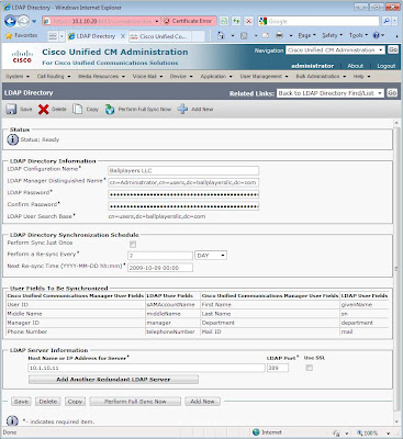
Next, configure LDAP Directory information under System > LDAP > LDAP Directory. Below is a screen shot.


Finally, provide the necessary credentials for LDAP Authentication under System > LDAP > LDAP Authentication. You can verify that your UCM is synchronizing with Active Directory by going to User Management > End User to verify that the system has been populated with the users.

2. Word of caution on the next steps…. While this is how I configured my phones, this process may not be the most expedient during the actual CCIE Voice Lab. Remember, time management is key. However, for learning purposes, here are the steps I followed for setting up the phones for New York and Los Angeles…

First, I begin be creating a CUCM group, “Ballplayers_Sub_Pub”, with the subscriber server first in priority.

Next, I created two Date/Time Groups, one for New York, and another for Los Angeles, with the appropriate timezone and NTP information.

Two Regions are then created, one for New York and one for Los Angeles, with the appropriate codecs assigned accordingly.
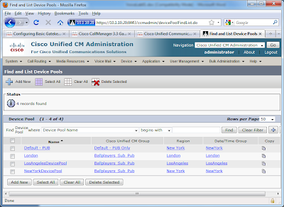
A Device Pool for both New York and Los Angeles is created. For each Device Pool, modify Cisco Unified Communications Manager Group, Date/Time Group, and Region. Below is the NewYorkDevicePool.
Lastly, I go to System > Cisco Unified CM and disable the Auto Registration previously configured in lab 1.2. This will come into play when we modify the Los Angeles phones for SIP.

3. At the conclusion of lab 1.2, the phones for New York and Los Angeles had registered with the Publisher (UCMPUB01) via auto configuration. By going to Device > Phone, the appropriate parameters for each phone can be modified. For New York SCCP phones, the following parameters are changed and/or configured:

Description > a helpful description for reference
Device Pool > select the device poolOwner User ID > select the end user
Then, proceed to configure the line settings:
Configure the Los Angeles SIP phones requires a few extra steps. First, since the phones for Arliss Michaels and Kobe Bryant auto-registered as SCCP, they first must be deleted.. This was why auto-registration was disabled. If the phone were removed while auto-registration still enabled, the phones would simply re-register. Hint, note the MAC address of each phone prior to deletion. Then, manually add each device as a SIP phone. The process is very similar to adding a SCCP phone, except you need to modify some of the Protocol Specific Information, notably the Device Security Profile and SIP Profile. For now, select the defaults available in CUCM.

Upon completion of adding the phones, modify the lines for Arliss and Kobe. At this point, phones should be able to call each other, whether within each location or too/from each location.

Monday, September 28, 2009

CCIE Voice Lab 1.2 – Initial Cisco Unified Communications Manager Configuration

Lab 1.2 will explore the initial Cisco Unified Communications Manager (CUCM) configuration and setup. I’ve built two CUCM virtual machines on a VMware ESX 3.5 server. CUCM 7.x release includes a “starter license”, which provided 150 DLUs and a 3 node license. Follow the instructions in the Unity Connection-CUCME Lab 3 – Unity Connection Installation on VMware ESX 3.5 post for the process of building CUCM on VMware ESX 3.5.

CCIE Voice Lab 1.2 Tasks
1. Activate all appropriate and necessary Network and Feature Services.

2. Ensure that the call processing cluster does not need to rely on DNS for any services.

3. Ensure that the interdigit timeout does not exceed 5 seconds.

4. Quickly provision the phones in New York and Los Angeles.

CCIE Voice Lab 1.2 Solutions
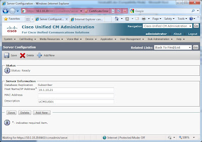
1. First step is to log into the publisher, UCMPUB01. From there, navigate to System > Servers. If your servers are listed by their hostname, click each one and change to their IP Address.


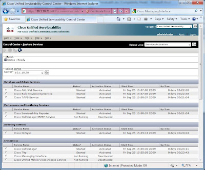
2. Next stop, visit the Cisco Unified Serviceability interface. From there, Tools > Control Center – Network Services and verify everything in functioning correctly.


3. Next, the Tools > Control Center – Feature Services in the Cisco Unified Serviceability interface shows that by default, these services are deactivated. By going to Tools > Service Activation, we can select each server and then activate accordingly. To understand which service to activate, go to the Help > This Page and review the information in Table 11-1.

After activating the appropriate services for the Publisher and Subscriber, you can verify status by navigating to Tools > Control Center – Feature Services in the Cisco Unified Serviceability.


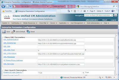
4. Returning to Cisco Unified CM Administration, go to System > Enterprise Parameters. Modify the Phone URL Parameters that reference UCMPUB01 to 10.1.10.20.


5. To modify the interdigit timeout, go to System > Service Parameters. Select the Publisher (10.1.10.20) in the Server drop down, followed by Cisco CallManager (Active) in the Service drop down. Look for the T302 Timer, and modify from the default 15000ms to 5000ms.

6. The easiest way to quickly provision phones is to enable auto registration. To accomplish this task, navigate to System > Cisco Unified CM and select the Publisher server. Use a phantom number range, such as 7000 to 7099, and uncheck the “Auto-registration Disabled on this Cisco Unified Communications Manager” box.


7. After a few minutes, the phones should register with UCMPUB01.