Showing posts with label CCIE Voice Lab 1. Show all posts

Friday, March 19, 2010

CCIE Voice Lab 1.12 – UCCX

We will configure Cisco Unified Contact Center Express in Lab 1.12.

CCIE Voice Lab 1.12 Tasks


1. Configure UCCX to work with CUCM using the following parameters:

a. CUCM AXL Username: use your CUCM Admin username and password

b. Cisco Unified CM Telephony Provider Configuration, User Prefix: uccxcti; create a password

c. RmCm Provider Configuration, User ID: uccxrmcm; create a password

d. NTP Server: NY VGWY

e. Number of HR session licenses: 3

f. Recording Count: 6

g. Number of Outbound seats: 6

h. Codec: G711

i. Cisco Unified CCX Administrator: Ari Gold (agold) and David Wright (dwright).

j. Use CTI Ports/DNs beginning with 1201.


2. Configure the auto attendant script to answer calls when a call arrives at 1300. However, when callers hit the AA, they should be greeted with “Welcome to Ballplayers LLC” followed by the default welcome AA. Do not modify the existing AA.


3. Configure an NY Mets ACD Queue that will be triggered when dialing extension 1010. When callers dial 1010, they should be greeted with “Welcome to Ballplayers LLC” followed by the default prompt. Ari Gold should have a new UCCX DN 1011; David Wright should have a new UCCX DN 1012. Ari should also take the call first, unless he is busy. Caller should hear Music On Hold while sitting in queue.


4. Ari and David should be able to log into ACD service from their phone without typing a username and password. Both should be in a ready state once he has selected the “Ready” softkey and remain ready as long has he hasn’t either logged out or selected the “not ready” softkey.


CCIE Voice Lab 1.12 Solutions

The CCIE Lab is notorious for wording task in such a way to as either “confuse” or trip up the test taker (at least this was the case when I took my Route/Switch lab). I’ve worded the tasks in Lab 1.12 to makes the student think about all of the tasks in this lab. For example, just because a particular task comes later, that doesn’t necessarily mean that the test taker must complete those tasks in that particular order.

Also note, the Administration Guide for Cisco Unified CCX and Cisco Unified IP IVR, Release 7.0(1) is only available on CCO as a PDF document. Therefore, I will refer to specific chapters during my explanations below.
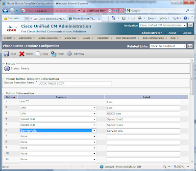

1. Prior to configuring UCCX, I begin by provisioning the user parameters in UC Manager; specifically adding the UCCX DNs for Ari Gold and David Wright, as configuring a new UCCX template. First, I create a new Phone Template for agents, and then associate this Phone Button Template with Ari’s and David’s phone.


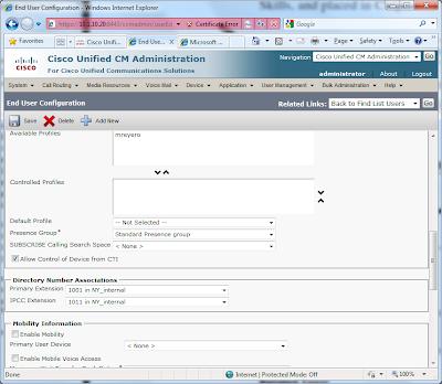
Next, I add the 1011 and 1012 lines to Ari and David phones, respectively. Finally, under User Management > End User, I associate these new DNs with both Ari and David as their IPCC Extension. See Guidelines for Configuring Agent Phones, page 4-16 of the Administration Guide for Cisco Unified CCX and Cisco Unified IP IVR, Release 7.0(1) for further details.

2. Before we can begin configuring either the AA or ACD, UCCX requires some basic setup. When logging into UCCX the first time, a setup wizard launches. During this wizard, you are prompted to provide the following configuration parameters:


UC Manager IP address: 10.1.10.20

AXL Username: Administrator

Password:

Installation of License

Cisco Unified CM Telephony Provider Configuration, User Prefix: uccxcti; create a password

RmCm Provider Configuration, User ID: uccxrmcm; create a password

NTP Server: NY VGWY

Number of HR session licenses: 3

Recording Count: 6

Number of Outbound seats: 6

Codec: G711

User Configuration: Ari Gold (UCCX Administrator) and David Wright.
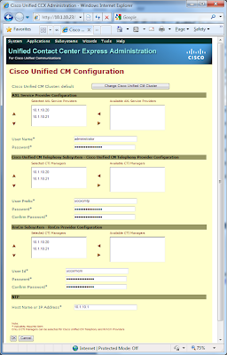


For additional information and details, refer to Provisioning Unified CM Telephony Subsystem, page 6-5 of the
Administration Guide for Cisco Unified CCX and Cisco Unified IP IVR, Release 7.0(1).
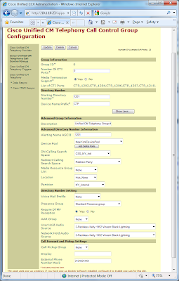
Next, configure the Cisco Unified CM Telephony Call Control Group under Subsystems > Cisco Unified CM Telephony.
See Adding a New Unified CM Telephony Call Control Group, page 6-9 of the Administration Guide for Cisco Unified CCX and Cisco Unified IP IVR, Release 7.0(1).


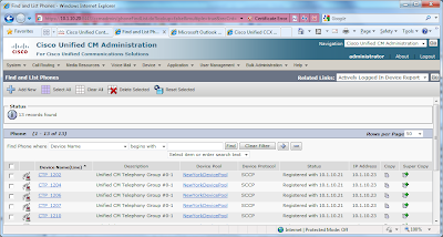
You can verify that the CTI ports are registered with UC Manager under Device > Phone.


3. There are a few things we need to do in order to work with the default AA script. First, record your prompt per the task. Refer to Recording and Uploading Prompt Files, page 10-12 of the Administration Guide for Cisco Unified CCX and Cisco Unified IP IVR, Release 7.0(1) for instructions on using the Microsoft Windows Sound Recorder in Windows XP. Then, upload your prompt in Applications > Prompt Management.
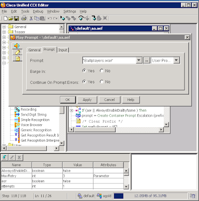

Next, launch your Cisco Unified CCX Editor. Open the Auto Attendant template under File > Open > C: > Program Files > wfavvid > Scripts > Template > IVR > Auto Attendant.aef. On the left side of the editor, expand the Media Folder and drag
“Play Prompt” in front of the existing “Play Prompt” in the script. Then, right-click this new prompt and select “Properties”. In the “Prompt” option tab, type the name of your Prompt in “quotations”.
Verify the script and then save it in the Script Repository > Default.


To configure the new AA script, go to Application > Application Management > Add a New Application. From the Add a New Application > Application Type drop-down, select Cisco Script Application, then next. Provide the necessary information for the Cisco Script Application and select Add.
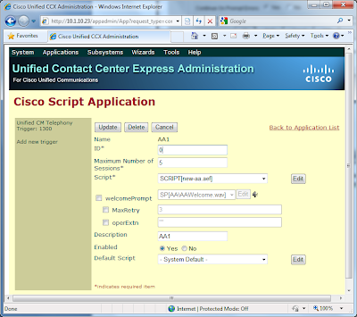
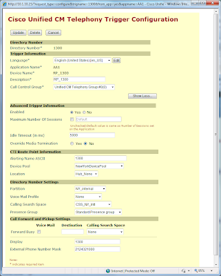
Lastly, we need to add a Trigger for this script. Under the Trigger Type drop down, select “Unified CM Telephony Trigger”. Then, provide the necessary Trigger Configuration information, and Add. At this point, you should be able to dial 1300, whereupon you will hear your custom prompt followed by the standard AA.

Refer to the Configuring Script Applications, page 9-3 of the
Administration Guide for Cisco Unified CCX and Cisco Unified IP IVR, Release 7.0(1) for additional information and guidance.


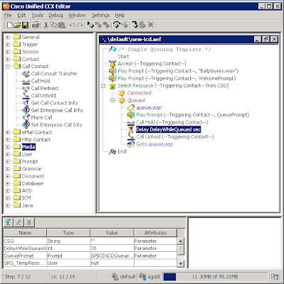
Configuring the ACD follows a similar process. Once again, launch the Cisco Unified CCX Editor. This time, open the ICD template under File > Open > C: > Program Files > wfavvid > Scripts > Template > Queuing > Simple Queuing.aef. As before, add a new “Play Prompt” step prior to the first one. However, in order for a call to hear MOH, you must add a Call Hold step and Call Unhold step before and after “Delay DelayedWhileQueued sec”. Verify the script and then save it in the Script Repository > Default.

5. Since UCCX Extensions have already been associated with users, there are two primary tasks left for configuring the NY Mets ACD queue; creating/modifying a script and then setting up another Cisco Script Applications.

Once again, open the
Cisco Unified CCX Editor, and select the ICD template. As with the AA script, modify the ICD script to include your custom welcome message. Next, in order for callers to hear MOH while in queue, you must add the “Call Hold” and “Call Unhold” steps to the queueLoop.


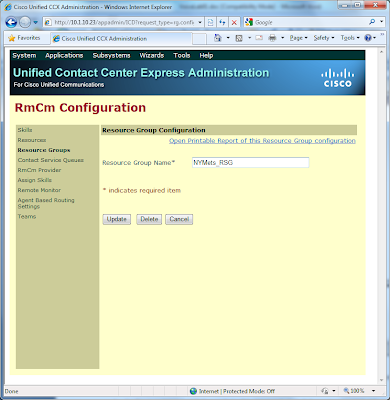
Next, in UCCX, go to Subsytems > RmCm and configure a Resource Group and assign the users to that Resource Group. Then, configure your CSQ, Script Applications, and Trigger.
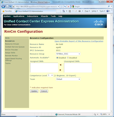
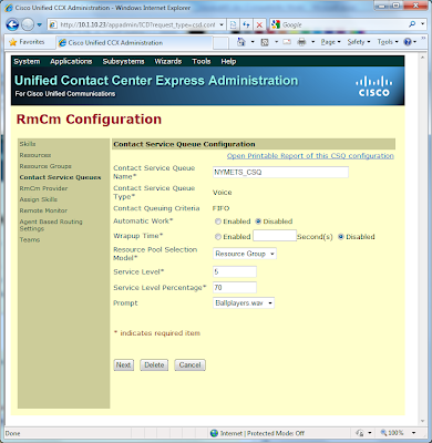
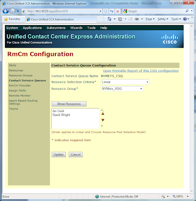
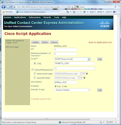




6. The last task involves the configuration of Cisco IP Phone Agent and a few system tweaks. You’ll notice that during the CSQ configuration, Automatic Work is disabled by default, which is what we want. Then, under system parameters, change the value of “Agent State after Ring No Answer*” from the default Ready to Not Ready.

To have Ari and David login into IP Phone Agent (IPPA), refer to the
Configure a "One Button Login" for IP Phone Agents example on CCO.

Monday, February 8, 2010

CCIE Voice Lab 1.11 – Unity Connection and CUE

In CCIE Voice Lab 1.11, the New York, Los Angeles, and London locations will be configured to support voice messaging and associated components.

CCIE Voice Lab 1.11 Tasks

1. Configure Cisco Unity Connection (CUC) integration with CUCM. You must integrate using SCCP. Use pilot 1170, directory number 1171 and 1172, and 1180 for MWI-on and 1181 for MWI-off.

2. Configure Unity Connection voicemail for all users in New York and Los Angeles. Users must be imported from CUCM. Ensure that the users in the directory are listed last name, first name. Accounts should be created with the following requirements:
a. No Limit for Failed Logons
b. Credential Never Expires
c. Minimum Credential Length: 5
d. Stored Number of Previous Credentials: 0
e. No Check for Trivial Passwords
f. User must be prevented from sending Broadcast Messages to Users

3. Configure an Auto Attendant for NY with DN 1000. Configure the AA so that when users press “0” they are routed to Ari Gold at ext. 1001. Business hours are 8AM – 6PM EST/EDT. Customize the greeting as follows:
a. Allow callers to press “4” to use the phone keypad to spell all or part of the last then first name of the Connection user that they want to reach.
b. At the end of the greetings, users should be sent to a Directory Handler. If a Caller Exits, he/she should be sent back to the NY Opening Greeting. If a caller provides No Input, No Selection or Presses Zero, the call should be routed back to Ari Gold’s mailbox.
c. After hours messages should also be stored in Ari Gold’s mailbox.

4. Configure an Auto Attendant for LA with DN 2000. Configure the AA so that when users press “0” they are routed to Arliss Michaels at ext. 2001. Business hours are 8AM – 6PM PST/PDT. Customize the greeting as follows:
a. Allow callers to press “4” to use the phone keypad to spell all or part of the last then first name of the Connection user that they want to reach.
b. At the end of the greetings, users should be sent to a Directory Handler. If a Caller Exits, he/she should be sent back to the LA Opening Greeting. If a caller provides No Input, No Selection or Presses Zero, the call should be routed back to Arliss Michaels’s mailbox.
c. After hours messages should also be stored in Arliss Michaels’s mailbox.

5. Configure a second line appearance on Ari’s phone using *1001. When Ari’s primary extension is busy, calls should roll to this number, followed by voicemail. This line should be able to access voicemail in Ari’s mailbox.

6. London CUCME users should use their local CUE for voicemail, with the following parameters: pilot 3170; and 3180 for MWI-on and 3181 for MWI-off. Create mailboxes for Jerry Maguire and David Beckham with blank passwords and PINS.

7. Create an AA in London using ext 3000. Ensure that callers in NY and LA can reach the AA via VOIP as well as PSTN dialing.


CCIE Voice Lab 1.11 Solutions

1. The Cisco Unified Communications Manager SCCP Integration Guide for Cisco Unity Connection Release 7.x is an excellent document for describing the tasks required to integrate CUC with CUCM. I more or less used the examples and naming conventions provided in Programming the Cisco Unified CM Phone System for Integrating with Cisco Unity Connection section of the Setting Up a Cisco Unified Communications Manager 7.x SCCP Integration with Cisco Unity Connection chapter.

Below is screenshot of the final page of the Cisco Voicemail Port Wizard.


After the wizard finishes, configure the Hunt List and Hunt Pilot.Then, add the MWIs, Voice Mail Pilot Number for the Voice Mail Ports, and Voicemail Profile, per the instructions in Programming the Cisco Unified CM Phone System for Integrating with Cisco Unity Connection.

Now, proceed to Creating a New Integration with Cisco Unified Communications Manager. Do not forget to add your Pub as an AXL Server under the Phone System Configuration, as well as adding Unity Connection as an Application Server in CUCM.

2. To modify “No Limit for Failed Logons”, “Credential Never Expires”, “Minimum Credential Length: 5”, and “Stored Number of Previous Credentials: 0”, modify the default “Voice Mail Authentication Rule” under System Settings > Authentication Rules.

Looking ahead to the AA configuration, it would be wise to create a new schedule under Systems Settings > Schedules. Then, apply this new schedule to the Templates > User Templates > voicemailusertemplate.

Next, to ensure that users cannot send Broadcast Messages to Users on This Server, verify that “User Can Send Broadcast Messages to Users on This Server” is not-checked under Templates > User Templates > voicemailusertemplate > Send Message Settings.

Finally, you can import users from CUCM from Tools > Import Users. Be aware, users in CUCM must have their primary extension define. Visit Creating Multiple User Accounts from Cisco Unified Communications Manager Users for a good overview. Keep in mind that when you import your users, they will inherit the system Timezone. For your LA based users, you will need to modify their Timezone to PST.

3. Now we are ready to create the AA for both New York and Los Angeles. The process if almost identical. Basically, I create two now Call Handlers, “NY-Opening-Greeting” at extension 1000 and “LA-Opening-Greeting” at extension 2000. Edit the Greetings and Caller Input to match the task requirements. I then created to new Directory Handlers, one for NY and another for LA. I edit the Caller Input for each based on the task requirements.

4. Task 5 is relatively straight forward. Create a new Voice Mail Profile for the *1000 extension with a Voice Mail Box Mask of 1000; this strip the “*”. When you add the *1000 dn to Ari’s Phone, make sure that you use this Voice Mail Profile on this line appearance.

5. We now move on to CUE. Given that I covered CUE extensively in the CUCME-CUE Labs, so I will not recap the details here. However, I did run into an issue, which I haven’t fully yet fixed….

Because the SIP dial peer to the AA in London is not H323, it does not register with the gatekeeper. Therefore, I cannot dial 73000 from either NY or LA to hit the AA in London. I tried adding the e164 via the alias commands under gatekeeper. However, this is only a temporary fix and will not work in the actual lab. When you reboot either the gatekeeper (NY) or the CUCME router (London), the CUCME (London) will attempt to register using a random port. Since the alias command uses a static port (either 1719 or random, depending on how you initialing configuring), the RRQ from the gateway will be rejected (RRJ) by the Gatekeeper. I’ve spent a fair number of hours trying to find a work around, nothing has successfully worked. For now, I am moving on. If anyone finds a resolution, please share!

Monday, December 28, 2009

CCIE Voice Lab 1.10 – Quality of Service

Quality of Service (QoS) will be the focus CCIE Voice Lab 1.10.

CCIE Voice Lab 1.10 Tasks

1. Ensure that Skinny traffic from New York to Los Angeles is set to DSCP CS3. Any and all markings should be done by the endpoint whenever possible.

2. Limit SCCP traffic in both New York and Los Angeles to 30k per endpoint, and exceed traffic should be remarked to AF11.

3. Configure the frame relay link between New York and Los Angeles as if it is a full T1 (1536kpbs) link. Ensure that MLP FLI is enabled on the link. Lastly, configure the QoS as follows:
a. Voice media traffic should have a 30% priority of link bandwidth;
b. Voice signaling traffic should be given 5% of the link bandwidth;
c. All other traffic should be treated with weighted fair queuing.

4. Configure the frame relay link between New York and Los Angeles as if it is a half- T1 (768 kbps) link, with the following QoS parameters:
a. Voice media traffic should have a 192K of link bandwidth prioritized;
b. Voice signaling traffic should be given 38K of the link bandwidth;
c. All other traffic should be treated with weighted fair queuing.

5. Ensure that the New York VGWY, Los Angeles VGWY, and London CUCME send signaling and media traffic at DSCP CS3 and EF respectively.

CCIE Voice Lab 1.10 Solutions

1. By default, SCCP DSCP values are set at CS3 in the CUCM Enterprise Parameters.


Next, identical QoS policies are configured on both the New York and London switches (3750 and NME-16ES-1G-P, respectively). First, enable QoS globally, then define the policed DSCP remarking:

mls qos
mls qos map policed-dscp 24 to 10


Then, create the appropriate access-list to identify the SCCP traffic, following by the class-map to match the traffic, and finally, the QoS policy.

!
access-list 101 permit tcp any any eq 2000
!
class-map match-all SCCP
match access-group 101
!
!
policy-map MARK-SCCP
class SCCP
set dscp cs3
police 30000 8000 exceed-action policed-dscp-transmit


The final step is to create an inbound service-policy for the switchports that have IP phones.

interface FastEthernet1/0/8
description newyork phones
switchport access vlan 11
switchport voice vlan 12
spanning-tree portfast
service-policy input MARK-SCCP


2. The QoS and Traffic Shaping described in task 3 requires the creation Modular QoS CLI, a Virtual Template, and Frame Relay traffic shaping on both the New York and Los Angeles routers. Note, the configurations are identical on both routers, with the exception of the IP Addressing on both sides of the link. The first step it to create the QoS policy.

class-map match-all SIGNAL
match ip dscp cs3
class-map match-all RTP
match ip dscp ef
!
!
policy-map NY-LA-QOS
class RTP
priority percent 30
class SIGNAL
bandwidth percent 5
class class-default
fair-queue

Next, create the Virtual Templates for both New York and Los Angeles. Below is the New York side of the link.

!
interface Virtual-Template102
bandwidth 1536
ip address 172.16.1.1 255.255.255.252
ip ospf network point-to-point
ppp multilink
ppp multilink interleave
ppp multilink fragment delay 10
service-policy output NY-LA-QOS
!

Then, create the frame relay traffic shaping policy, and associate the Virtual Template with the Frame Relay sub-interface, and associate the frame relay traffic shaping policy.

!
map-class frame-relay FRTS-NY-LA
frame-relay cir 1536000
frame-relay bc 15360
frame-relay be 0
frame-relay mincir 1536000
!
interface Serial0/2/0
no ip address
encapsulation frame-relay
frame-relay traffic-shaping
frame-relay lmi-type cisco
!
interface Serial0/2/0.102 point-to-point
description frame relay link to Los Angeles
ip ospf network point-to-point
frame-relay interface-dlci 102 ppp Virtual-Template102
class FRTS-NY-LA
!


3. The QoS configuration between New York and London is slightly different, since the tasks do not instruct us to configure MLP LFI. For this link, the QoS policy-map is defined, reusing the previously configured class-maps. Then, a frame-relay traffic shaping policy is defined, with the QoS service-policy tied to it. Lastly, the FRTS policy is associated with the frame-relay sub-interfaces between New York and London.

!
policy-map NY-LNDN-QOS
class RTP
priority 192
class SIGNAL
bandwidth 38
class class-default
fair-queue
!
!
map-class frame-relay FRTS-NY-LNDN
frame-relay cir 768000
frame-relay bc 7680
frame-relay be 0
frame-relay mincir 768000
service-policy output NY-LNDN-QOS
!
!
interface Serial0/2/0.103 point-to-point
description frame relay link to London
ip address 172.16.1.5 255.255.255.252
ip ospf network point-to-point
frame-relay interface-dlci 103
class FRTS-NY-LNDN
!

4. By default, the MGCP and H323 gateways send media (RTP) marked as ef and signaling marked as af31.

To verify New York, first issue:

newyork#sh dial-peer voice 100 include DSCP
ip media DSCP = ef, ip media rsvp-pass DSCP = ef
ip media rsvp-fail DSCP = ef, ip signaling DSCP = cs3,
ip video rsvp-none DSCP = af41,ip video rsvp-pass DSCP = af41
ip video rsvp-fail DSCP = af41,

Then, modify the markings for each VOIPdDial-peer. Dial-peer 100 is shown below.

newyork(config)#dial-peer voice 100
newyork(config-dial-peer)#ip qos dscp cs3 signaling

In Los Angeles, verify by issuing a “show mgcp” to view the defaults.

losangeles#sh mgcp
!
MGCP media (RTP) dscp: ef, MGCP signaling dscp: af31


To modify, issue

losangeles(config)#mgcp ip qos dscp ef media
losangeles(config)#mgcp ip qos dscp cs3 signaling


then verify

losangeles#sh mgcp
!
MGCP media (RTP) dscp: ef, MGCP signaling dscp: cs3

CUCME marks voice media traffic at DSCP value EF by default and voice signaling DSCP value CS3 by default. These parameters may be changed under the telephony-service CLI parameters. A “show telephony-service” in London verifies the values.

london#sh telephony-service
CONFIG (Version=7.1)
=====================
Version 7.1
Cisco Unified Communications Manager Express
For on-line documentation please see:
http://www.cisco.com/en/US/products/sw/voicesw/ps4625/tsd_products_support_series_home.html

ip source-address 10.1.32.1 port 2000
ip qos dscp:
ef (the MS 6 bits, 46, in ToS, 0xB8) for media
cs3 (the MS 6 bits, 24, in ToS, 0x60) for signal
af41 (the MS 6 bits, 34, in ToS, 0x88) for video
default (the MS 6 bits, 0, in ToS, 0x0) for serviceservice directed-

Wednesday, December 16, 2009

CCIE Voice Lab 1.9 – Conferencing, Transcoding, and MTP Resources

CCIE Voice Lab 1.9 requires the set up and configuration of Conferencing, Transcoding, and MTP Resources for Ballplayers, LLC.


CCIE Voice Lab 1.9 Tasks

1. For New York users, configure conferencing resources on the New York VGWY first, followed by the PUB, then SUB.

2. For LA users, configure conferencing resources on the LA VGWY first, followed by the PUB, then SUB.

3. Allow a maximum of 8 users in a conference bridge session. Ensure that when the Conference Controller leaves an AdHoc Conference, the call is dropped.

4. For each location, configure a MeetMe conference bridge using an x100 DN, where x= the appropriate dial plan for each location.

5. For both NY and LA, configure local transcoding resources.

6. Configure the London CUCME router to provide local transcoding and both MeetMe and AdHoc conferencing resources for users. Users should have a distinct join and leave tone.

7. Enable MOH for all three locations. Ensure that MOH files are available in G.711ulaw, G.729, and Wideband. Ensure the MOH loops.


CCIE Voice Lab 1.9 Solutions

The tasks in lab 1.9 require configuration in both the CUCM and VGWYs. The IOS commands will be covered first, followed by the CUCM, and lastly the London CUCME configuration.

1. The first step is to configure the DSP services on the New York and Los Angeles. The configurations on both VGWYs are nearly identical, with one exception pertaining to MOH in Los Angeles. That exception will be discussed separately later.

Essentially, you enable dspfarm services, followed by creating dspfarm profiles, and then associating those profiles with SCCP. The NY VGWY configuration is as follows:

newyork#sh run
!
voice-card 0
dspfarm
dsp services dspfarm
!
!
sccp local Loopback0
sccp ccm 10.1.10.21 identifier 2 version 7.0
sccp ccm 10.1.10.20 identifier 1 version 7.0
sccp
!
sccp ccm group 1
associate ccm 1 priority 1
associate ccm 2 priority 2
associate profile 2 register NY-VGWY-TRANS
associate profile 1 register NY-VGWY-CONF
!
dspfarm profile 2 transcode
codec g711ulaw
codec g711alaw
codec g729ar8
codec g729abr8
codec g722-64
codec g729br8
codec g729r8
maximum sessions 2
associate application SCCP
!
dspfarm profile 1 conference
codec g711ulaw
codec g711alaw
codec g729ar8
codec g729abr8
codec g729r8
codec g729br8
codec g722-64
maximum sessions 2
associate application SCCP
!

newyork# sh sccp
SCCP Admin State: UP
Gateway Local Interface: Loopback0
IPv4 Address: 1.1.1.1
Port Number: 2000
IP Precedence: 5
User Masked Codec list: None
Call Manager: 10.1.10.21, Port Number: 2000
Priority: N/A, Version: 7.0, Identifier: 2
Trustpoint: N/A
Call Manager: 10.1.10.20, Port Number: 2000
Priority: N/A, Version: 7.0, Identifier: 1
Trustpoint: N/A

Transcoding Oper State: ACTIVE - Cause Code: NONE
Active Call Manager: 10.1.10.20, Port Number: 2000
TCP Link Status: CONNECTED, Profile Identifier: 2
Reported Max Streams: 4, Reported Max OOS Streams: 0
Supported Codec: g711ulaw, Maximum Packetization Period: 30
Supported Codec: g711alaw, Maximum Packetization Period: 30
Supported Codec: g729ar8, Maximum Packetization Period: 60
Supported Codec: g729abr8, Maximum Packetization Period: 60
Supported Codec: g722r64, Maximum Packetization Period: 30
Supported Codec: g729br8, Maximum Packetization Period: 60
Supported Codec: g729r8, Maximum Packetization Period: 60
Supported Codec: rfc2833 dtmf, Maximum Packetization Period: 30
Supported Codec: rfc2833 pass-thru, Maximum Packetization Period: 30
Supported Codec: inband-dtmf to rfc2833 conversion, Maximum Packetization Period: 30

Conferencing Oper State: ACTIVE - Cause Code: NONE
Active Call Manager: 10.1.10.20, Port Number: 2000
TCP Link Status: CONNECTED, Profile Identifier: 1
Reported Max Streams: 16, Reported Max OOS Streams: 0
Supported Codec: g711ulaw, Maximum Packetization Period: 30
Supported Codec: g711alaw, Maximum Packetization Period: 30
Supported Codec: g729ar8, Maximum Packetization Period: 60
Supported Codec: g729abr8, Maximum Packetization Period: 60
Supported Codec: g729r8, Maximum Packetization Period: 60
Supported Codec: g729br8, Maximum Packetization Period: 60
Supported Codec: g722r64, Maximum Packetization Period: 30
Supported Codec: rfc2833 dtmf, Maximum Packetization Period: 30
Supported Codec: rfc2833 pass-thru, Maximum Packetization Period: 30
Supported Codec: inband-dtmf to rfc2833 conversion, Maximum Packetization Period: 30


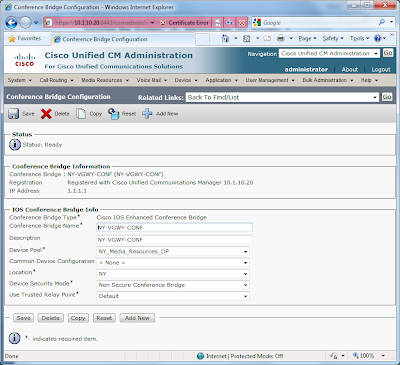
2. Borrowing from the concepts of Gateways > Route Groups > Route Lists, first define the conference bridges and trancoding resources.


Next, define Media Resource Groups (MRG) and assign the conference bridges and trancoding resources accordingly. I’ve created a MRG for each location; New York and Los Angeles.


The MRGs are then added to a Media Resource Groups List (MRGL); one for each location. Watch the ordering, so that HW resources are used prior to SW resources.


Finally, assign the appropriate MRGL to the appropriate Device Pool for each location.


3. Configuring conferencing and transcoding resources for the London CUCME router is nearly identical to as configuring the resources on the NY and LA VGWYs. However, SSCP is associated with CUCME under telephony-service, rather than the UCMs. Rather than revisit the configuration, refer to CUCME-CUE Lab 7 – CUCME Conferencing & Transcoding. I assigned dn 3100 for the MeetMe bridge and 3101 for the AdHoc bridge.

4. There are few tricks for the MOH, specifically for the LA SIP-based location. First, make sure that the “Cisco IP Voice Media Streaming App” is activated under Cisco Unified Serviceability.

Next, make sure that G.711ulaw, G.729, and Wideband are selected under the Service Parameters > Cisco IP Voice Media Streaming App.


The MOH servers are then assigned to the MRGs; see the NY MRG screenshot above. To quickly assign the same MOH file to all phones, go to Device > Device Settings > Common Device Configuration, and create a custom configuration. I’ve chosen “1952 Vincent Black Lightning” from Alt-County band “Reckless Kelly”.


This newly created “MOH Common Device Configuration” can now be assigned to each phone.


When testing MOH up to this point, I noticed the phones based in Los Angeles were not receiving MOH. After some research, I discovered the MOH for SIP phones needs to terminate on an MTP resource on the LA VGWY. Therefore, one additional dspfarm profile is required for the LA VGWY, along with its companion configuration in UCM. This MTP is then assigned to the LA MRG.

losangeles#sh run
!
sccp ccm group 1
associate ccm 1 priority 1
associate ccm 2 priority 2
associate profile 3 register LA-VGWY-MTP
associate profile 1 register LA-VGWY-CONF
associate profile 2 register LA-VGWY-TRANS
!
!
dspfarm profile 3 mtp
codec g711ulaw
maximum sessions software 2
associate application SCCP
!


Wednesday, November 25, 2009

CCIE Voice Lab 1.8 – SRST and AAR

This lab will challenge the candidate to configure Survivable Remote Site Telephony (SRST) and Automated Alternate Routing (AAR).

CCIE Voice Lab 1.8 Tasks

1. Configure the Los Angeles router for SIP SRST. Phone should display a “SRST Fallback Active” message.

2. While in SRTS mode, calls to 911 or 9-911 should be route immediately. You may only use on outgoing dial-peer to accomplish this task.

3. Preserve the dial-9 for PSTN access during an SRST scenario.

4. While in SRST node, users should be able to dial 4-digit to NY and 7+3… to London. Calls should be routed over the PSTN without the need for users to add prefixes to these locations. You may not use a Prefix in the dial-peer, and this task must be accomplished using a minimal amount of commands.

5. Ensure that users at New York and Los Angeles are able to call each other when bandwidth limits are met.


CCIE Voice Lab 1.8 Solutions

1. Tasks 1 – 4 involved setting up SRST for SIP phones. A very good reference document is the Cisco Unified SIP SRST System Administrator Guide . First, start by configuring the basis SRST commands on the Los Angeles VGWY.

losangeles#
!
voice register global
system message SRST Fallback Active
max-dn 10
max-pool 10
dialplan-pattern 1 2135432... extension-length 4
!
voice register pool 1
translation-profile incoming emergency
id mac 0021.D8B9.BC72
number 1 2001
codec g722-64
!
voice register pool 2
translation-profile incoming emergency
id mac 0021.D8BA.2373
number 1 2002
codec g722-64
!
!
application
global
service alternate default
!
!
ccm-manager fallback-mgcp
!
!
call-manager-fallback
max-conferences 4 gain -6
transfer-system full-consult
!


2. To configure 911 and 9-911 routing, configure 9-911 translation rule and translation profile. Then, apply the translation profile to the voice register pool configurations. Lastly, create a 911 pots dial-peer.

!
voice translation-rule 1
rule 1 /9911/ /911/
!
!
voice translation-profile emergency
translate called 1
!
!
voice register pool 1
translation-profile incoming emergency
!
voice register pool 2
translation-profile incoming emergency
!
!
dial-peer voice 911 pots
description SRST 911
destination-pattern 911
port 0/1/0:23
forward-digits all
!

3. Task 3 and 4 involve the creation of additional pots dial-peers. However, you need to create some additional translation rules and a translation profile to accommodate the 4-digit and 7+4-digit dialing requirements.

!
voice translation-rule 2
rule 1 /\(1...\)/ /212432\1/
rule 2 /^7\(3...\)/ /207654\1/
!
!
voice translation-profile SRST
translate called 2
!
!
dial-peer voice 2 pots
description SRST Long Distance
destination-pattern 91[2-9]..[2-9]......
incoming called-number .
direct-inward-dial
port 0/1/0:23
!
dial-peer voice 3 pots
description SRST Local 10-Digit
destination-pattern 9[2-9]..[2-9]......
port 0/1/0:23
!
dial-peer voice 4 pots
description SRST London
destination-pattern 901144T
port 0/1/0:23
!
dial-peer voice 5 pots
description SRST 4-digit to NY
translation-profile outgoing SRST
destination-pattern 1...
port 0/1/0:23
!
dial-peer voice 6 pots
description SRST 7+4-digit to London
translation-profile outgoing SRST
destination-pattern 73...
port 0/1/0:23
!


4. Test the SIP SRST fallback by shutting down the WAN link from Los Angeles to New York. First, the phones should failover to SRST and display the “SRST Fallback Active” message. The “show voice register all” will provide the SRST configuration. Lastly, place some test calls, using 4-digit, 7+4-digit, and PSTN dial patterns.

losangeles# sh voice register all
VOICE REGISTER GLOBAL
=====================
CONFIG [Version=7.1]
========================
Version 7.1
Mode is srst
Max-pool is 10
Max-dn is 10
Outbound-proxy is enabled and will use global configured value
System message is SRST Fallback Active
timeout interdigit 10
network-locale[0] US (This is the default network locale for this box)
network-locale[1] US
network-locale[2] US
network-locale[3] US
network-locale[4] US
user-locale[0] US (This is the default user locale for this box)
user-locale[1] US
user-locale[2] US
user-locale[3] US
user-locale[4] US

VOICE REGISTER DN
=================

VOICE REGISTER POOL
===================
Pool Tag 1
Config:
Mac address is 0021.D8B9.BC72
Number list 1 : Pattern is 2001
Proxy Ip address is 0.0.0.0
DTMF Relay is disabled
kpml signal is enabled
Translation-profile incoming emergency

Dialpeers created:

dial-peer voice 40003 voip
destination-pattern 2001
redirect ip2ip
session target ipv4:10.1.22.16:5060
session protocol sipv2
digit collect kpml
codec g722-64 bytes 160
after-hours-exempt FALSE

dial-peer voice 40004 voip
destination-pattern 2135432001
redirect ip2ip
session target ipv4:10.1.22.16:5060
session protocol sipv2
digit collect kpml
codec g722-64 bytes 160
after-hours-exempt FALSE

Statistics:
Active registrations : 1

Total SIP phones registered: 1
Total Registration Statistics
Registration requests : 1
Registration success : 1
Registration failed : 0
unRegister requests : 0
unRegister success : 0
unRegister failed : 0


Pool Tag 2
Config:
Mac address is 0021.D8BA.2373
Number list 1 : Pattern is 2002
Proxy Ip address is 0.0.0.0
DTMF Relay is disabled
kpml signal is enabled
Translation-profile incoming emergency

Dialpeers created:

dial-peer voice 40001 voip
destination-pattern 2002
redirect ip2ip
session target ipv4:10.1.22.17:5060
session protocol sipv2
digit collect kpml
codec g722-64 bytes 160
after-hours-exempt FALSE

dial-peer voice 40002 voip
destination-pattern 2135432002
redirect ip2ip
session target ipv4:10.1.22.17:5060
session protocol sipv2
digit collect kpml
codec g722-64 bytes 160
after-hours-exempt FALSE

Statistics:
Active registrations : 1

Total SIP phones registered: 1
Total Registration Statistics
Registration requests : 1
Registration success : 1
Registration failed : 0
unRegister requests : 0
unRegister success : 0
unRegister failed : 0


5. The final tasks require the configuration of setup and configuration of Automated Alternate Routing (AAR). AAR is disabled by default on CUCM, so the first step is to configure the AAR Service Parameters in CUCM by choosing System > Service Parameters > Cisco Call Manager.

Next, configure an AAR group. Since my Adtran PSTN simulator does not accept the “1” for long distance calls, I simply prefix a “9”. In the CCIE Voice Lab, and possibly your home lab, you may need to prefix “91”.


AAR Partitions and Calling Search Spaced are then created for AAR. Below is the NY AAR CSS, which included the NY AAR LD Partition.


Two new Route Lists are created, one for each location. These new route lists used for the AAR only point to the local PSTN gateways. Below is the NY AAR RL.


Create two new route patterns for ten-digit NY to LA and LA to NY calling (remember, my Adtran PSTN simulator does not accept “1+10-digit” dialing). Link these new route patterns to the appropriate AAR Route lists.


Finally, add the appropriate AAR Calling Search Space and AAR Group to each phone and AAR settings for line.


For testing, I temporary modify the bandwidth between locations to 24kbps (one call). Nail up two calls between each location. With the second call, the phone should display “Network Congestion, Rerouting” and the call should be placed via the PSTN.

Thursday, November 19, 2009

CCIE Voice Lab 1.7 – Voice CODECs and CAC

Now that the dial plan has been properly configured between New York, Los Angeles, and London, this lab will focus on configuring the proper CODECs between locations as well as Call Admission Control.

CCIE Voice Lab 1.7 Tasks
1. Calls within a location should use G.722 wideband.

2. Calls between locations should use G.729.

3. Allow five concurrent calls between New York and Los Angeles.

4. When calls from London to either New York or LA use the IP WAN, they should negotiate G.729. However, in the event that there are any transcoding issues, only one G.722 call should be allowed across the WAN.


CCIE Voice Lab 1.7 Solutions
The tasks in this lab are relatively simple. A good discussion on locations, regions, and CAC are covered Call Admission Control chapter of Cisco Unified Communications SRND Based on Cisco Unified Communications Manager 7.x. You can also click here and here for some old, but decent Gatekeeper configuration examples.

1. The first step is to create regions for New York, Los Angeles, and London and assign the codecs to be used between each location. You may have done some of these task earlier when configure phones.

2. Next, create Device Pools and assign the Regions accordingly.

3. Next, assign your newly create device pools to devices.

4. Create your locations and assign the appropriate bandwidth. Make sure you understand how CUCM allocates bandwidth for a particular codec. Then, assign these locations to the Phones.


5. On the gatekeeper, configure the proper bandwidth settings.

newyork#
!
gatekeeper
zone local newyork ballplayersllc.com 1.1.1.1
alias static 10.1.10.21 1720 gkid newyork gateway voip ras 10.1.10.21 33072 e164 2002 e164 2001 e164 1003 e164 1002 e164 1001
bandwidth total zone newyork 128
no shutdown


6. Finally, nail up some calls between locations to exceed the bandwidth limits. On CUCM phones, once bandwidth limits are hit, the phones should display “Not Enough Bandwidth”. On the gatekeeper, “debug ras” and “show gatekeeper zone status” are useful commands.